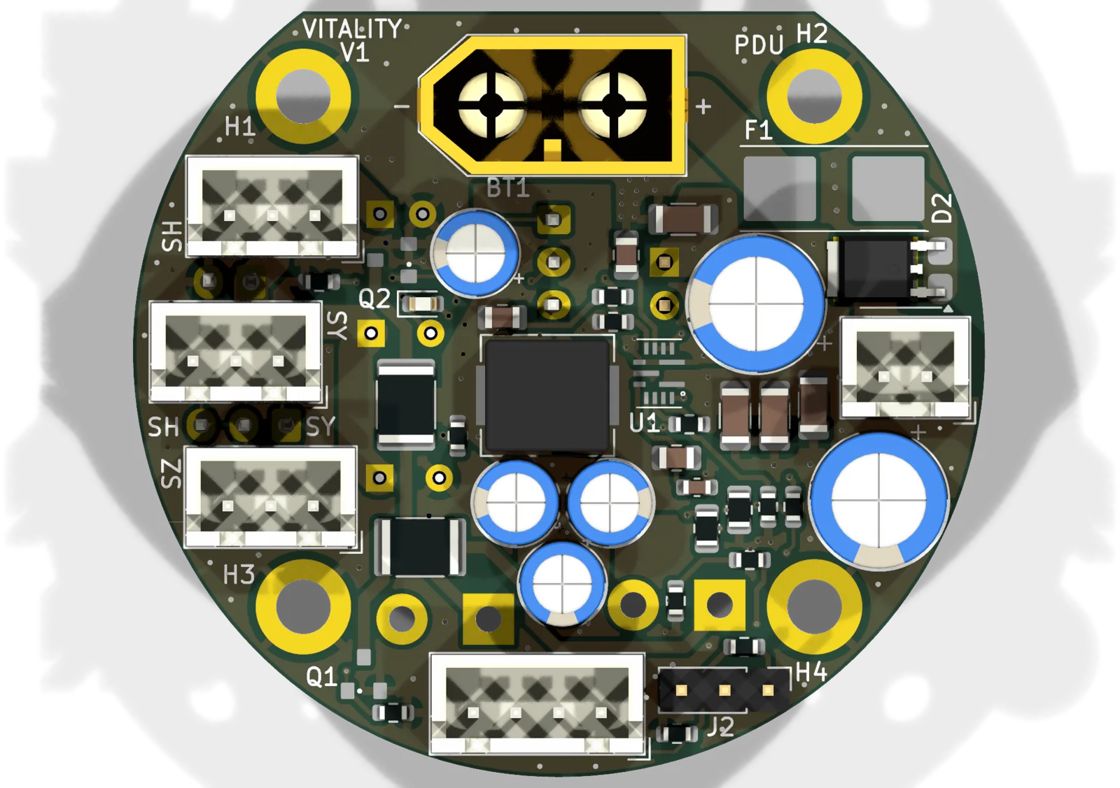
ANVIL H1 / power avionics
IT6 proposal under team reviewVITALITY PDU
VITALITY distributes the ANVIL H1 flight pack to the avionics: a 5 A fuse, the power switch, reverse-polarity protection and a 5 V buck converter for the flight computer, the servos and the Wi-Fi bridge, plus battery-voltage sensing for the firmware. The motor ESCs run directly from the pack. I own the power avionics: I assembled and integrated the board, brought its schematic in line with the fitted parts in IT5, and designed the IT6 revision.
My work
- Bring-up and integrationAssembled the board, reconciled the RP2040 pin map between the schematics and the firmware, and measured the battery-sense path on the bench.
- IT5 documentationBrought the schematic in line with the fitted parts: sense-divider values, 3S labelling and warnings against 6S on the modified sense branch. No part, track or footprint moved.
- IT6 redesignA PMOS reverse-polarity transistor in place of the Schottky diode, battery sensing through an ADS1115 read over I2C, and a 3.3 V regulator for that sensing.
- SimulationConverter and transient studies in SIMBA. In LTspice, IT6 drops 89 mV at 2 A instead of 670 mV through the diode, and its battery-sense error during a servo current step is 9.4 times lower than IT5. The worst-case connection inrush, simulated without cable inductance, still exceeds the transistor's pulse rating.
IT6 power path
IT6 · proposal under team reviewFabrication follows team validation.
Documentation
Revisions
- Fitted board
- IT3 PCB reworked for an XT60 connector, with the IT5 component values.
- IT5 schematic
- VITALITY V1 PDU, IT5 (PDF, 1 page). Documentation revision matching the fitted values; not fabricated as such.
- IT4 schematic
- VITALITY V1 PDU, IT4 XT60 (PDF, 1 page). Previous revision: its sense-divider values and 6S labelling no longer match the flying board.
- Layout
- Board layout up to IT5 by a teammate; the documents keep the original title block.